67P/Churyumov-Gerasimenko. A Single Body That’s Been Stretched- Part 32
ESA/Rosetta/MPS for OSIRIS Team MPS/UPD/LAM/IAA/SSO/INTA/UPM/DASP/IDA/SGS/PSA&ESDC/Scute1133
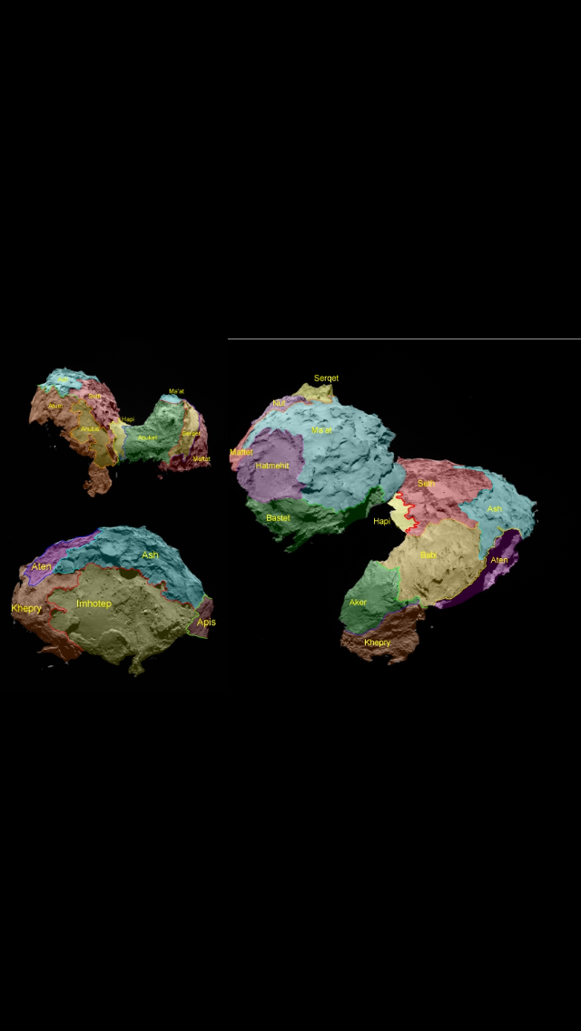
Photo 2- the ESA comet regions map to help with locating the regions referred to below.
Part 31 presented the lattice of stretch vectors in the so-called slab A extension and the red triangle. The stretching of 67P was due to the ‘centrifugal’ force brought about by the comet spinning up to somewhere around a two- to 3-hour rotation period. The spin-up would have occurred via asymmetrical outgassing. Alternatively a close pass at Jupiter some way under the 220,000 km Roche limit would supply the stretching force via differential g accelerations instead of spin-up.
Part 31 stated, “there are other areas nearby that show similar stretch vector signatures that are orientated at a slightly different angle from this lattice.”
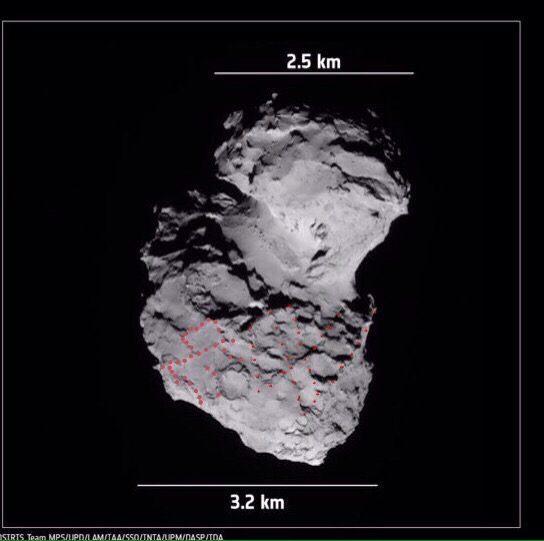
If we trek across Ash from the red triangle and round the perimeter of the slab A extension, we cross through the lattice and end up in an area behind the three sink holes. Here, we find an area with lines that resemble the lattice but they are fainter, broken and further apart. Also, their aggregate direction seems to be at a slightly different angle from the lattice orientation around the red triangle. It all looks a bit woolly.
Photo 3- the smudged lattice lines in Ash (larger dots).
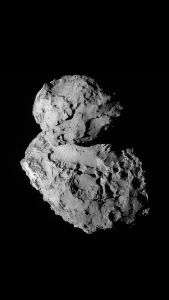
Photo 4 – the Ash matches behind the three sink holes. Includes unannotated version.
Photos 4 and 6 have narrative keys so the end of the key is denoted by the symbol ‘/////’.
Fuchsia- the fuchsia circle is the large sink hole at one end of the flat area of Site A. The two horseshoe arcs below it depict the other two sink holes set in line behind it and towards the back of Site A. They are smaller, shallower and joined to the main one. The three together form a trench with bulbous sides.
Long terracotta line- the shear line for orientation purposes. The terracotta L-shapes in Ash are stretch matches (see below).
Yellow next to shear line- the beginning of the Site A ‘crater’ perimeter. The rest is left out so as not to clutter the photo.
Orange- missing slab B (Babi-Part 9).
Bright green- on the right running away from the shear line- this is the right hand perimeter of the slab A extension. It’s contiguous with one long side of the red triangle. Bright green is also used for the triad of matching bright green dots (see below) because when nested they sit almost at the opposite end of the slab A extension.
All other coloured dots, which are all below Site A and sitting in the Ash region, depict specific features that are repeated on the three recoiled layers.
Red arrows- these depict the directions in which the matches flare out across Ash and therefore betray the the direction of the stretching forces acting on them.
/////
We can see the matches flaring out wider as they extend down Ash, away from the Site A crater rim and sink holes. If we replay the stretch movie backwards, the bottom layer of matches moves up Ash, contracting slightly along its length (horizontally in this view) as it does so. It scoops up the second line as it passes it and then the two nested lines move further up Ash. Again, they contract across their length as they approach the third line of matches and nest with them. This time, the horizontal contraction is more marked and means that the red, blue and dark green matches get lost in the squeeze, leaving just the outside two to join together: the terracotta L-shape and the bright green triad. The focus of the contraction is the third sink hole which is the second one from the main, large sink hole. This means that:
1) The stretch vector lattice does extend further across Ash and all the way to site A.
2) The whole of Ash is one giant recoil area. That at last explains why the back rim of Site A continues on in a perfect arc along the back rim of the slab A extension- all the way to the red triangle (see photo 5, below). Both areas were subjected to the same stretching and recoil event. Ash is simply an onion layer that slid back under the influence of the stretch vector after decoupling from its counterpart a long way further up the body and somewhere on site A (and the slab A extension). That beautifully smooth arc betrays the subtly changing orientation of the stretch vectors across Site A, the slab A extension and Ash. This may be the reason that Ash looks a bit like a crumpled blanket. It didn’t lose material and in fact consists of excess, flaccid folds as a result of material that slid back. For regular readers who can stitch together all the references to the Slab A extension morphology since Part 22, this has now almost fully explained its morphology: the scalped skin split in two. Half is plastered against Anuket and the other half recoiled back to this curved line and is now part of Ash. The tear was about midway across. It was acknowledged as not being fully understood back in Part 22 and said to be a work in progress. It was stated that it must have been subjected to the same process as site A but what that process was remained a mystery. The answer is recoil and in retrospect, it looks rather obvious. All those references regarding the demise of the slab A extension will be collated into one post fairly soon, along with some extra evidence.
3) The three sink holes are orientated in line with the average direction of these newly discovered stretch vectors that flare out down Ash. Since all the matches converge on the third sink hole, it means that this sink hole and the second one behind it had to have at least been under tension along this vector. Since the vector is in line with the alignment of the holes, it’s reasonable to suggest that the holes delaminated along that line, from one big hole into three holes. Indeed, all delaminated strata either side of the sink holes is delaminated in this same stretch direction (see photo 6, lower down).
4) The stretch vector change betrayed by the Ash recoil curve is radial, meaning the vectors are focussed (nearly) on one point, right next to the north pole. That’s a huge clue for stretching via the centrifugal force of spin-up.
Photo 5- the Ash recoil showing the neat curve where the Ash onion layer recoiled to.
Yellow- portion of Site A (the missing slab A crater) up to where its back rim merges with the slab A extension back rim.
Bright green- the slab A extension back rim that continues on from where it merges with the Site A back rim.
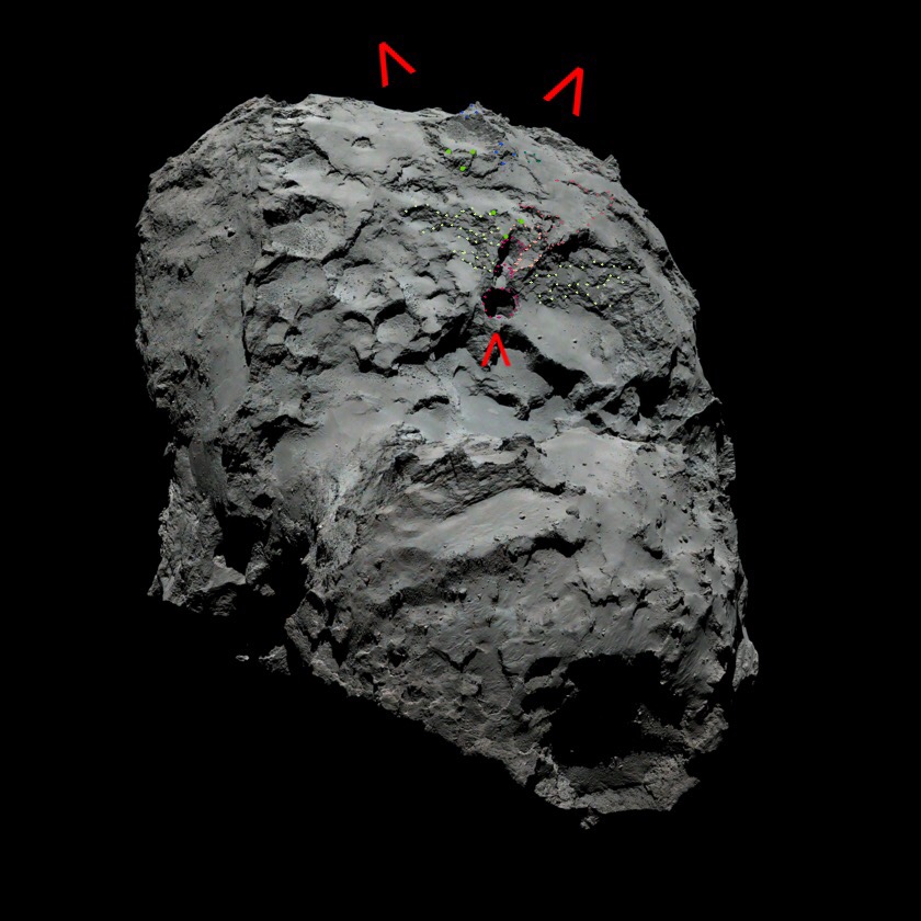
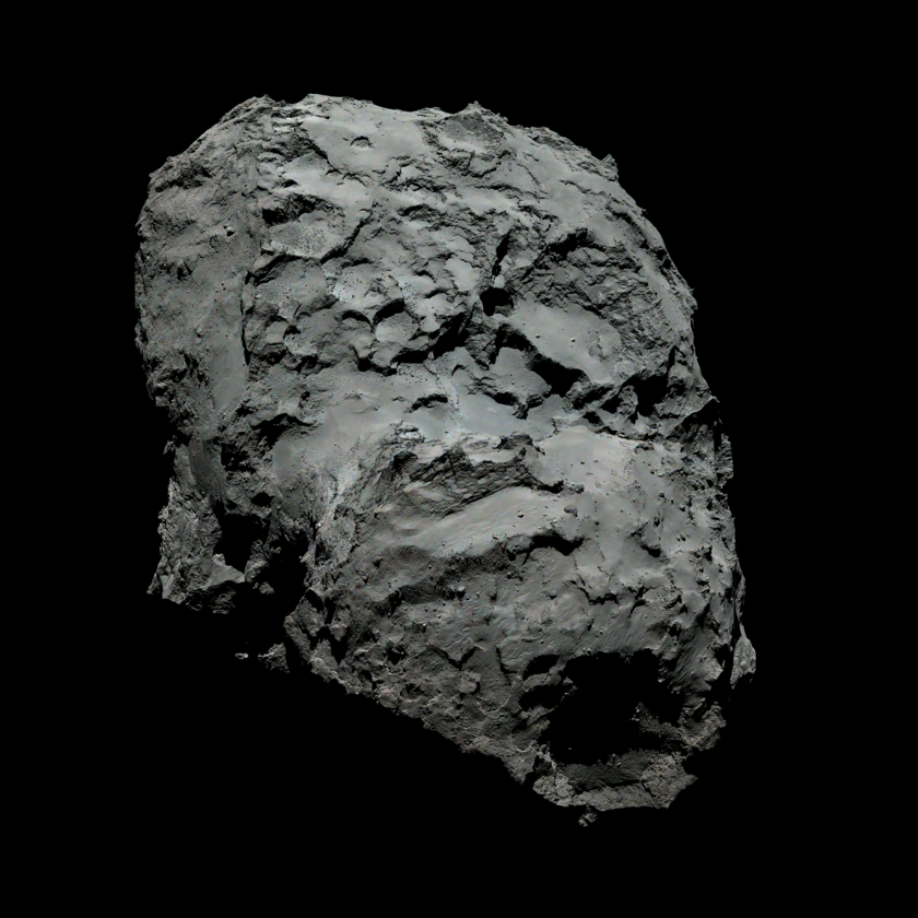
Photo 6- the delaminated layers next to the three sink holes.
ESA/Rosetta/MPS for OSIRIS Team MPS/UPD/LAM/IAA/SSO/INTA/UPM/DASP/IDA/SGS/PSA&ESDC/Scute1133
Fuchsia- the three sink holes. The main one is nearest to us and the delaminated ones are shown as horseshoe arcs beyond it. Looking at the floor level of the second hole, it’s on the same level as the large, flat expanse of Site A to the right as well as the smaller expanse to the left (at the bottom of the dotted terraces). This is a strong clue that the side walls of the main sink hole slid back along this fracture plane thus revealing the floor of the second sink hole which was previously sitting under the slid-back strata. It is therefore not a sink hole at all but the sliced top of the main sink hole, sitting on a newly exposed flat expanse. The same process would apply to the third sink hole, the only difference being that the revealed floor of that hole was another stratum or sub stratum further up from the second hole. Despite not being sink holes, after all, we’ll continue to call all three “sink holes” for the time being because they are called that by everyone who is interested in 67P. Even the main hole will eventually be shown not to be a sink hole- at least not in any conventional definition of the term whereby a cavity slowly forms and the roof collapses.
Red arrows- the upper pair show the direction of travel of the fanning-out matches, thus betraying the stretch vector that pulled them along those two paths. They point upwards because we’re looking from the opposite direction to photo 4 where they were pointing downwards. The single, lower arrow is pointing at the large sink hole. More importantly, it’s pointing in the direction along which the line of three sink holes is arranged. And this direction is in the average direction of the other two arrows. Hence the three sink holes were under a tensile stress force in this direction while everything around them was actually moving back down the comet under that same tensile force (proven by the matches). It’s therefore reasonable to suggest that the holes were also delaminating in that direction.
Bright green, blue, dark green and terracotta- these are the same features as in photo 4 but viewed from the exact opposite direction and from lower down. So they are converging towards us in a foreshortened perspective. The yellow and red dots are left out because they’re whited out here. Also the ‘lower’ dark green dip in the other photo is invisible here. The ‘lowest’ terracotta feature (highest here) is almost unrecognisable due to foreshortening so it’s left unannotated for fear of obliterating it. It continues beyond the second terracotta match in a zig zag.
Light orange- this and the first terracotta L-shape match that touches it were depicted as one terracotta L-shape in photo 4. That’s because it was fuzzier and in shadow in that photo. Here, it’s divided into the initial seating area, which is the pale orange dots, and the first terracotta match that slid back from it. You can see that the first terracotta match is a right angle with a thick finger of material. If you reverse the stretch movie, the finger slides towards us and clicks into place over the finger depicted by the pale orange dots. Its right angled part then clicks into place by curving round the back of the third hole but it may have just gone straight across the back of the bright green dots.
Pale green- strata that delaminated in the same direction as the average tensile force (stretch) vector. That would be the same direction as the delaminating holes. There are terraces of multiple matches fanning out on either side of the holes.
/////
Photo 6 basically shows everything in the vicinity of the sink holes getting yanked back, away from our viewpoint towards and across Ash. All this material would have originally been nested together with the three holes themselves also nested together.
THE LARGE, ISOLATED CRATER IN ASH MAY BE RELATED TO THE SINK HOLE
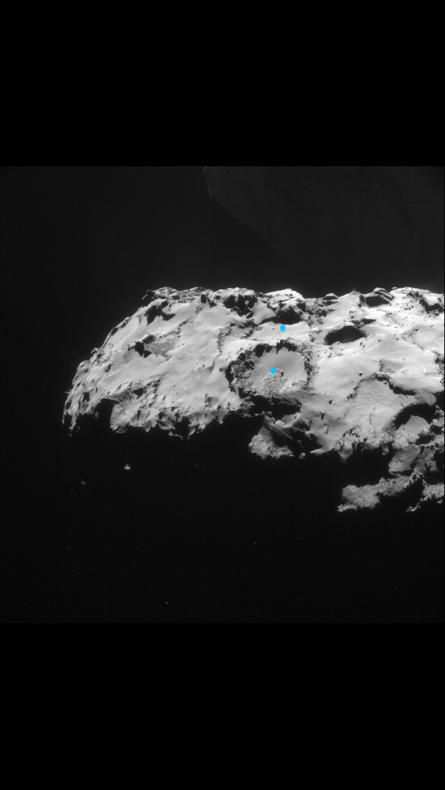
Photo 7- the crater in Ash. It has a light blue dot in its centre. Its twin in the ‘flared matches’ second tier is beyond it, also dotted light blue. Photo 4 also gives a good view of it. In that photo it’s got the dark blue matches either side.
There’s a match in photo 4 that wasn’t annotated. It would have cluttered up the image too much. That strangely isolated crater in the middle of Ash is sitting right in the middle of the matches. It’s the only large, circular crater on the comet with a completely intact rim. It’s also absolutely constrained to rise up Ash with the matches around it. And when we look at photo 4 again we can see that there’s a big circle right above it, in the correct direction of movement. It’s not just sited anywhere further up and in the right direction but it’s shadowing its L-shaped terracotta match on the other side of the flared set. In other words, the layer it delaminated from is the same as the the one from which its partner L-shape delaminated from before they both slid and flared another level down. The same principle should work with the next layer up. The L-shape has already been matched to the side of the third sink hole. If the crater behaved as it seems it did, sliding with the L-shape from the second to the third level, then it must surely have slid with the L-shape from the first to the second level. That means it was crammed right against the L-shape at ‘level 1’ and that in turn suggests it was sitting right on top of the third sink hole (presumably when it was an incipient sink hole). It would seem remarkable for a crater to move that far and stay intact. But the matches already constrain it to move from its circular, level 2 twin to its current position so if it had to move from there it’s not so implausible for it to have moved the whole way. And since we are saying that the three sink holes delaminated and that crater in Ash has now been traced to the third hole, it’s just as conceivable that it originally sat over the main sink hole before it delaminated into three.
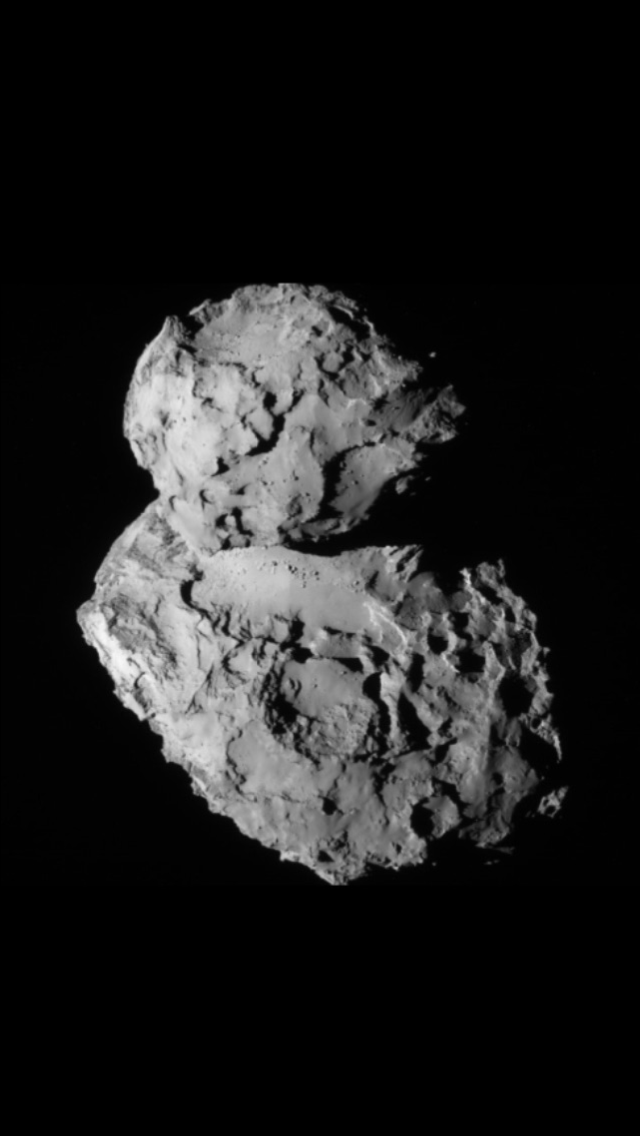
As a check, one can look at the unannotated version of photo 5. If you concentrate on that smooth curve forming the back rim of the slab A extension, that betrays the stretch vector or tensile force vector because that’s the curve along which it found its equilibrium after springing back. The tensile stretch force would be at 90° to the curve. If you draw a line between the crater and the main sink hole, whether it’s straight or via its slightly kinked matched path, it crosses the curve at 90°. If you replayed the stretch movie in reverse, the crater would always be headed for the large sink hole.
PHOTO CREDITS FOR NAVCAM PHOTOS:
Copyright ESA/Rosetta/NAVCAM – CC BY-SA IGO 3.0
To view a copy of this licence please visit:
All dotted annotations by Scute1133.
PHOTO CREDITS FOR OSIRIS PHOTOS:
-Original image provided as .IMG file in the archive delivery from : ESA/Rosetta/MPS for OSIRIS Team MPS/UPD/LAM/IAA/SSO/INTA/UPM/DASP/IDA
-Original image processed by ESA/Rosetta/SGS/PSA&ESDC to create image for Archive Image Browser
All dotted annotations by scute1133.

